
Dohle Ray – from a boost to a heavy fuzz
August 26th, 2022 — First units
You can find complete schematics, simulations and design files at dohlemusic/The-Ray (github.com)
When we designed the Ray, we initially wanted to accomplish a great warm bluesy sound. We wanted that huge dynamic range and detail of 12AX7 tube you can find in Fender amps, but in a compact form factor, without building an actual tube into the pedal. You might find some tube stompboxes, but they are often underpowered. There are some rarer, no longer produced tubes that run off of 9 or 12V, but most require over 100V and starving them rarely creates good results. We needed a better solution.
Fortunately there is a modern component that meets these criteria – it’s a JFET transistor. In principle they operate similarly, with far lower bias voltage, but there are many differences that cause them to sound different. Here we will not focus on the differences, since we want to primarily introduce it to the basic principles of how our pedal works and what you can do to modify it.
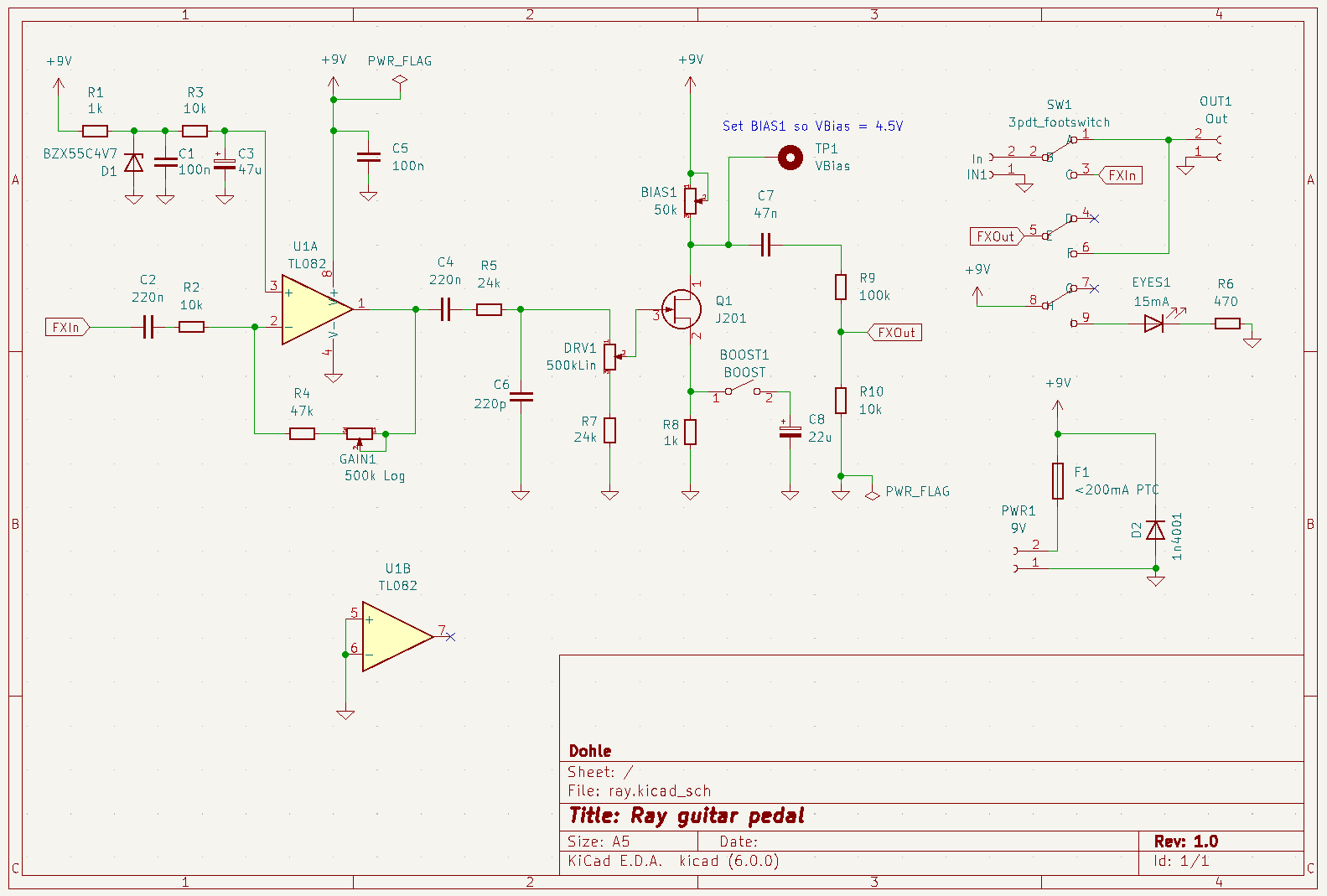
Detailed Ray schematic
As you can see, the pedal is pretty simple. On the conceptual level, it consists of two main stages – the first one is the op-amp and the other one is a classical J201 JFET transistor known for its nice and warm sound.
The Omp-Amp stage
The opamp (denoted as U1 on the schematic) stage is fairly simple to understand if you have basic knowledge in electronics – we use NE5532 or 4562, but you can change it to any pin-compatible opamp you want that runs from 9V – like the widely available TL072, TL082, LM358 and many others. This is perhaps the easiest modification you can introduce in the pedal to change the sound slightly, since we mount the opamp on a socket. Changing the opamp might have a subtle impact on the sound. All you need to do is to ideally use heavy tweezers to pull it out of the socket or pry it from the bottom (be careful to pry it from both sides to avoid bending the pins too much).
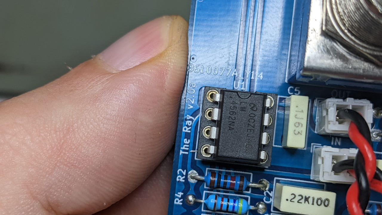
Detailed view of the opamp, you can remove it without soldering from the socket it was inserted into
The opamp is configured in inverting mode, for improved rejection of power supply and cable noise. We drive it fairly high – the maximum gain is roughly -51x. This is still not enough to cause clipping in some guitars, but it is important to boost the signal enough to cause the distortion once it is amplified with the J201 JFET (Q1 on the schematic). If you want to drive this stage even heavier, you can change R4 resistor to a higher value, or you can use a 1M logarithmic potentiometer (GAIN1) instead of the existing 500k.
Perhaps an interesting solution we used is how we bias the op-amp. Since we power it between 9V and ground, the non-inverting input (denoted as + on the U1A) has to be at 4.5V roughly. This way, the “virtual ground”, or the crossing point of all waveforms amplified by this opamp is at 4.5V and it can operate correctly from a single supply. A common solution to achieve it is to use two resistors that form a voltage divider, but we decided to use a zener diode for improved stability. You can read more about it in this amazing article.
The JFET stage
We use a J201 JFET transistor in self-biasing mode to amplify the output of the op-amp even more – so much that we cause it to clip, forming a fuzz effect. But that’s not everything – the gain curve of the JFET is non-linear and this part of the circuit was inspired with a so-called Fetzer Valve. The details of a similar JFET stage are described in huge detail here.
The easiest modifications of this stage are changing the bias voltage to cause assymetric clipping and change the DRV1 potentiometer to a higher or lower value (e.g. using a 1M linear potentiometer will cause a significantly heavier distortion).
The bias voltage is factory callibrated to be always 4.5V – it can be set by turning the BIAS1 potentiometer and measuring the voltage between the VBias test point and ground while the pedal is connected to a 9V power supply.
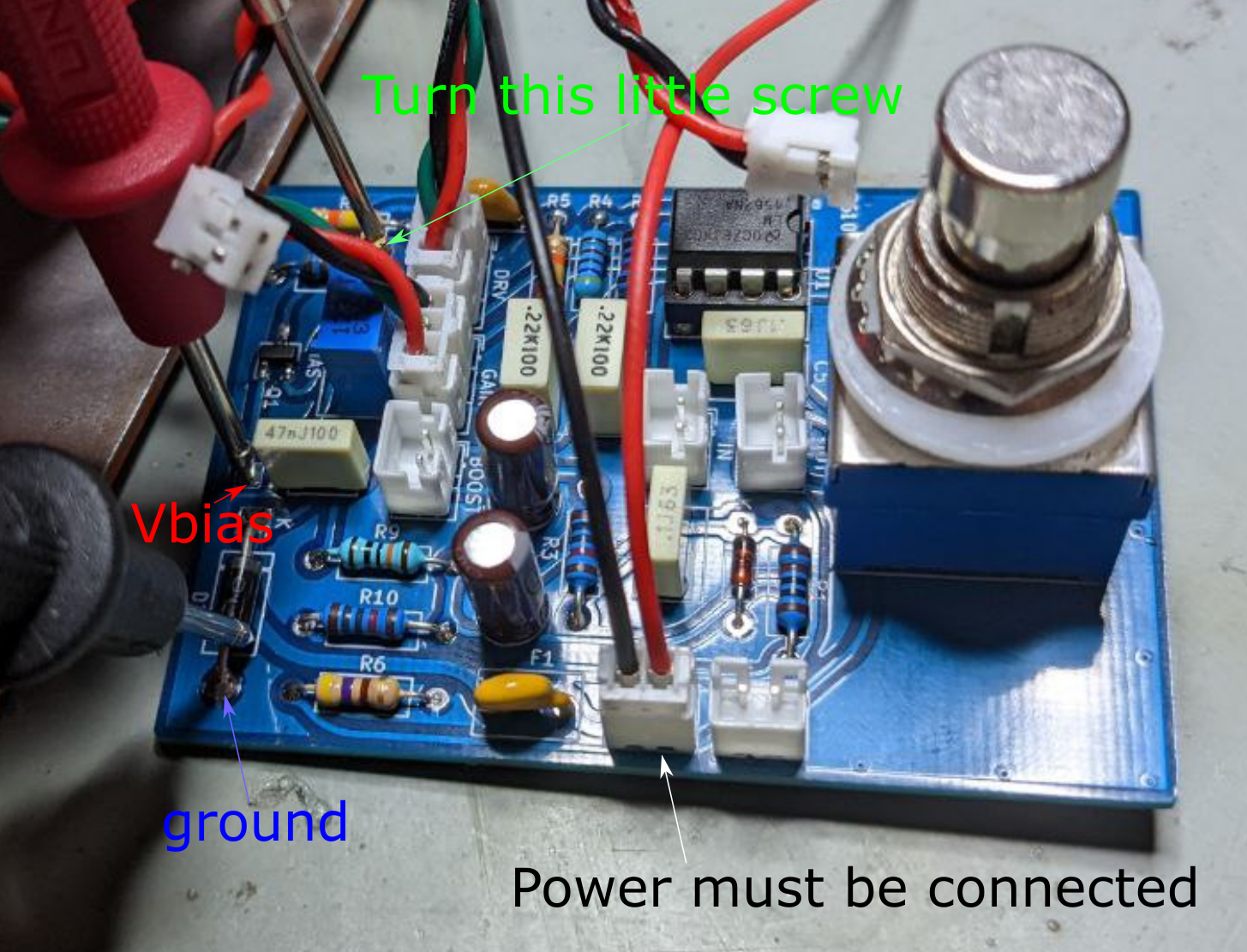
The voltage between the red (VBias) and blue (ground) point should measure 4.5V, but for assymetrical clipping, you can change it by turning the screw (marked with green arrow). Power supply and potentiometers must be connected for this procedure to work. You can disconnect the input and output audio jacks and LEDs