
Hardware design is no easy feat. Compared to software where hitting CTRL+Z or recompile is free, if you make a mistake with hardware, it can be quite pricey. For example if you make an error in the circuit board and order it, it often takes over a week before it arrives. Shipping alone can cost $20, while the PCB is only like $2. It gets even worse when you would outsource the manufacturing of the housings. Minimal orders are rarely less than 20 or so pieces and with such small orders, one piece can easily cost over 20 bucks. Therefore, it’s necessary to introduce a process that allows you to reduce mistakes to minimum.
Our first electronic designs started as simulations in LTSpice – it’s a free, old looking, yet incredibly powerful program, that allows you to fully simulate complex analog electronics. You can even tell it to process your own sound recordings and output an audio file, so you can actually hear the circuit you’re designing!
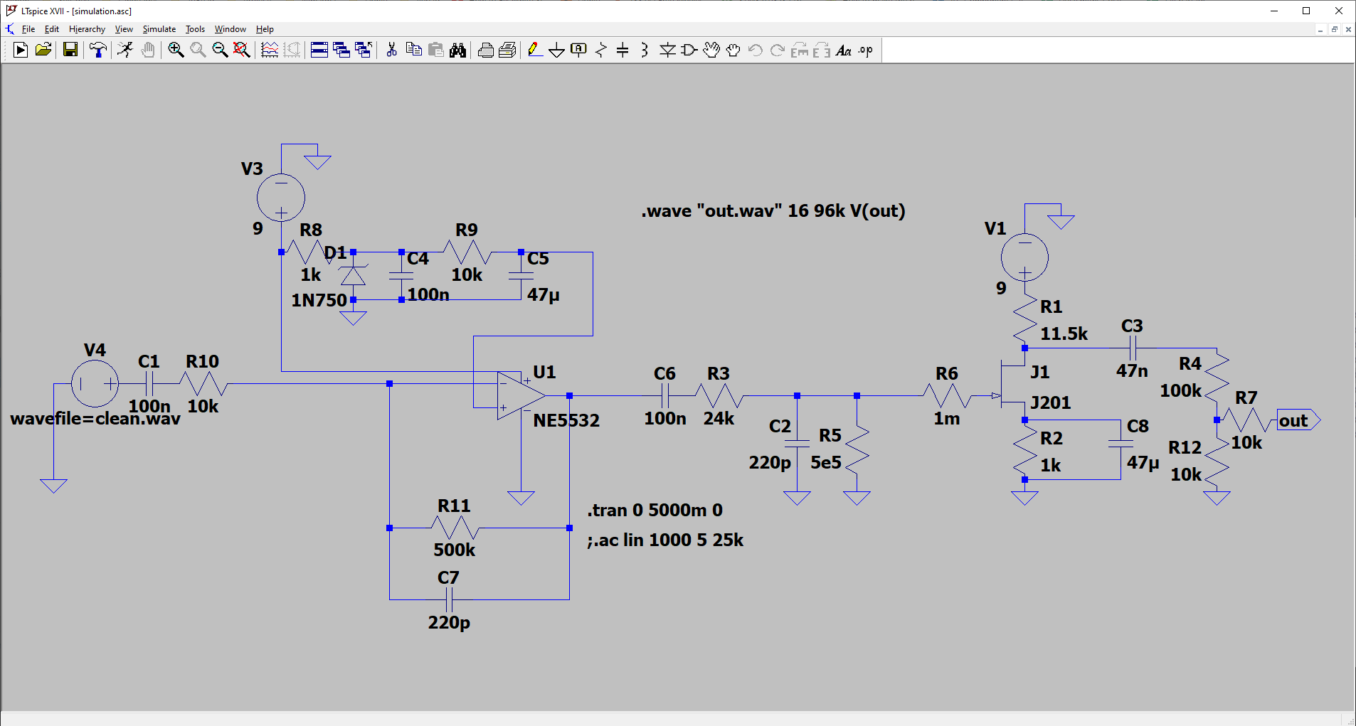
Sound demos in the simulation (first is clean input, second is distorted output, it’s loud!)
After we’re done with the simulations, we sometimes prototype the entire product or sections of it on either breadboards, or we build simple PCBs at home to save costs (and the planet). Here’s how the Ray pedal looked at the very beginning!


Once we’re confident things are working, we proceed into the initial design in KiCAD. It quickly became our favorite electronics design program, as it is open source and offers really nice features that allow you to quickly create complex designs and ensure they will work correctly.


")
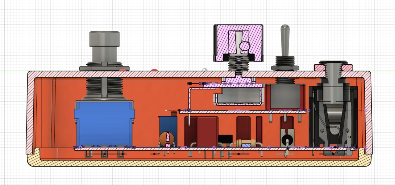
This new stacked design, required a much more careful placement of the components, to ensure every single bit and piece will fit perfectly into the enclosure. Fortunately, Fusion 360 came with help.
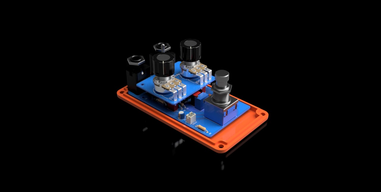
Thanks to the 3D CAD program, we were able to carefully place the components on the existing housing design. We got a lot of ready 3D models of elements such as the knobs from https://grabcad.com/ and from the official manufacturer webpages, which saved us a lot of work. Once we were sure everything will fit, we could export the outlines of the PCB into KiCAD and work on the electronics once again.